-
Edge Position Control Systems(Sensors)
- Sensor / Electric Type Diagram
- Autowide Sensor AWE280A
- Photohead PH22VAS for vacuum environments
- High-temperature EPC sensor HE120A (for transparent webs)
- Ultrasonic Sensor UH05
- CMOS Linear Sensor SLH30
- Design Position Control DPC
- PHOTOHEAD PH16B / PH21
- PHOTOHEAD PH22
- Ultrasonic Autowide Sensor UHW051
- Ultrasonic Autowide Sensor UHW280
- Ultrasonic Autowide Sensor UHW500 / 700
- LINE FOLLOWER HEAD LH19
- LINE FOLLOWER HEAD LH110
- LINE FOLLOWER HEAD LH500
-
Edge Position Control Systems(Electric type)
- Sensor / Electric Type Diagram
- Guide roller mechanism (Electric type)
- AC servo actuator A353
- AC servo actuator A032
- AC servo actuator A152-□□□-20
- Motor-Driven Actuator K50 K50/A
- Liteguide Controller AE550/AE560
- Linear Actuator K300-200-20
- Compact Guide Roll Mechanism PGR series
- Compact Guide Roll Mechanism LCD series
- Guide Roll Mechanism
- Liteguide Controller AE1000
- Motor-Driven Actuator K12 series
- Motor-Driven Actuator K62 K62/A
- Motor-Driven Actuator K80
-
Edge Position Control Systems(Hydraulic type)
-
EPC related components
-
Tension Control Systems
- Tension Control System Diagram
- Intrinsically safe explosion-proof MB tension sensor
- MJ tension sensor (for vacuum environment) MJ**VAS
- MJ tension sensor (for vacuum environment) MJ**V
- Tension Controller TC920V
- Tension Controller TC680A/D
- Open loop Tension Control System TCD030T
- Tension Meter TM310T
- Tension Meter TM340
- MG Tension Sensor
- MJ Tension Sensor
- CJ Tension Sensor
- MB Tension Sensor
- Electro-Pneumatic Converter EN40
- Other related equipment
-
Automaic Register Control Systems
-
Print-to-cut Register Control Systems
-
Other Related Equipment


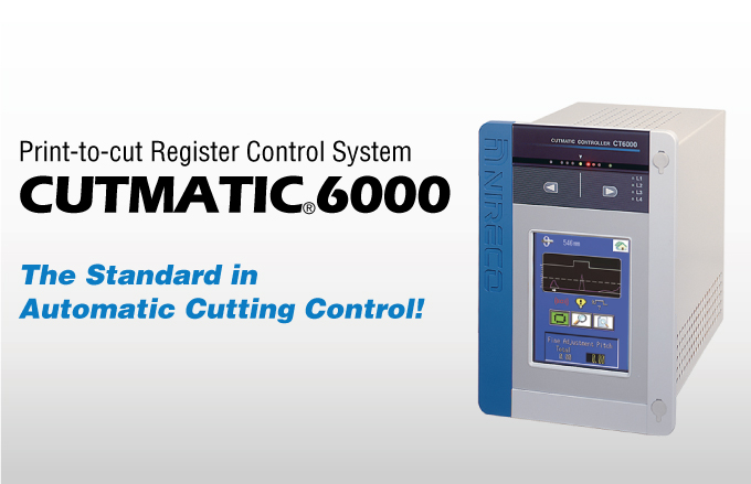
Print-to-cut Register Control System CT6000
Overview
Unrivaled Reliability and Operability!
Introducing the Print-to-cut Register Control System
From small food wrapping machines to large offset rotary presses, print-to-cut register control system Cutmatic CT6000 features cut positioning control of any sheeter and folder, face-back matching, pre-print sheeting, and overprint. Significant improvements in performance have been achieved through high-speed processing and the ability to select the optimum control mode (Control A, B and C) for each web operation. Implementing a LCD touch panel that functions as both a display and a means of inputting data has simplified the panel, improving operability.
Feature
-
Mark search function
The mark search function recognizes part of a pattern as a mark using a time-tested conventional controller.
-
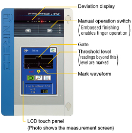
LCD touch panel both enables operation and shows information
The LCD touch panel enables the data necessary for an operation to be entered, and displays various parameters, gate mark waveforms, deviations, repeat lengths and other information. The color screen makes it easy to understand the operating status of the controller.
-
A panel designed with operability in mind
The frequently-used motor operation switch has a user-friendly design that maintains a conventional sheet switch, which enables finger operation by the operator. This has also reduced the frequency with which the touch panel is used, extending its life.
-
High processing speed
A single-chip microprocessor guarantees high-speed processing. (50% UP)
-
Fail-safe circuit
The system automatically stops, reducing paper waste, when normal operation is impossible such as when signals from the sensor cannot be detected or when the web speed slows down.
-
Built-in check function
The controller is equipped with a self-diagnostic function to verify operation in the event of a breakdown. As the line speed and the encoder pulse count can be displayed, the user can check whether the encoder is functioning normally and identifying malfunctioning areas has become easier than ever before.
-
Deviation display and output
By displaying the measured deviation rate (cutting discrepancy) on the touch panel as a graph, movements in the print-to-cut register can be instantaneously confirmed. It is also possible to record the deviation rate by analog voltage. (±5V DC)
Configuration
System Diagram
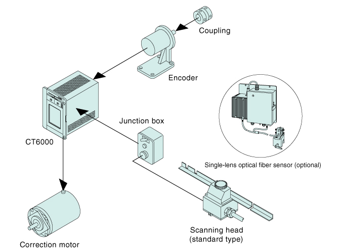
Controller
Operating under microprocessor control, the controller processes electric signals from the scanning head and the encoder. Control mode, gain, etc. can be set to control parameters. The correction motor is driven by controller correction signals.
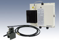
Optical fiber sensor
The optical fiber sensor was developed to enable detection at a constantly stable level, further improving the detection capability of a conventional S/H (sample/hold) circuit. The sensor uses a halogen lamp, which produces a high color temperature, and provides an outstanding color rendition. The sensor is superb at detecting marks with pale color combinations and adapts well to special webs. The circuit has also been designed to extend the life of the lamp, which has increased 1.7 times (5,000 hours). All of these improvements have made the sensor extremely easy to use.
Encoder
The encoder is an absolute no contact photoelectric unit that is directly connected to a cutter or plate cylinder drive shaft. It is controlled by the A, B and Z phases and monitors the synchronization and speed of the plate cylinder.
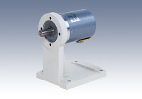
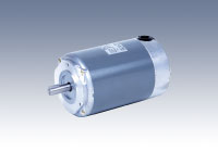
Correction Motor
The correction motor normally drivers the register roller (or the compensator roller) to adjust web length between the final control unit and the cutter in an inline configuration. The cutter mechanism is controlled using a correction motor to operate a differential gear.
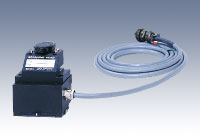
Scanning Head
The Scanning head incorporates a silicon photo diode, lamp, lens assembly and amplifier. Scanning head signals undergo high-speed automatic processing in the controller microprocessor to ensure automatic compensation of fogging of the scanning head window due to ink smudges, paper dust or slight changes in register mark density.
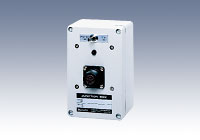
Junction Box
This terminal box relays signals between the scanning head and the controller. It houses the scanning head lamp drive circuit and the mark catch verification lamp. * Not required for optical fiber
Specifications
System Specifications
| Line speed | 10~1000m/min |
|---|---|
| Cylinder speed | 10~2000rpm |
| Cylinder size | 100~2500mm |
| Detection accuracy | ±0.01mm |
| Control speed | 2 mm/s (along web path) |
| Control operation | Control A, Control B, Control C |
| Correction count setting | 1 to 32 times |
| Deviation display range | 0.01 to 1.00 mm variable |
| Alarm | 0.01 to 9.99 mm variable |
| Control A : This control mode predicts the number of revolutions required for the current deviation level to converge according to the setting for the distance between the sensor and the drive roll. It is mainly suited to offset printing (standard). Control B : This control mode uses proportional gain and differential gain. It is mainly suitable for processing machines and low-speed printing presses. Control C : This mode is for controlling die cut rollers. It is suitable when directly driving die cut rollers or gravure plates. |
|
Controller Specifications
| Power voltage | 100 to 240V AC automatically switched, single phase 50/60Hz |
|---|---|
| Power consumption | 100VA (excluding motor) |
| Ambient temperature | 0 to +50˚C |
| Mass | 7kg |
| Mounting | Panel mounted |
Contact Us
Please use this form to submit your inquiries, feedback and/or requests to NIRECO.
